
AIQLAB Campus
QUBIT
An FPGA-based platform for the physical emulation, control, and real-time observation of a qubit’s state.
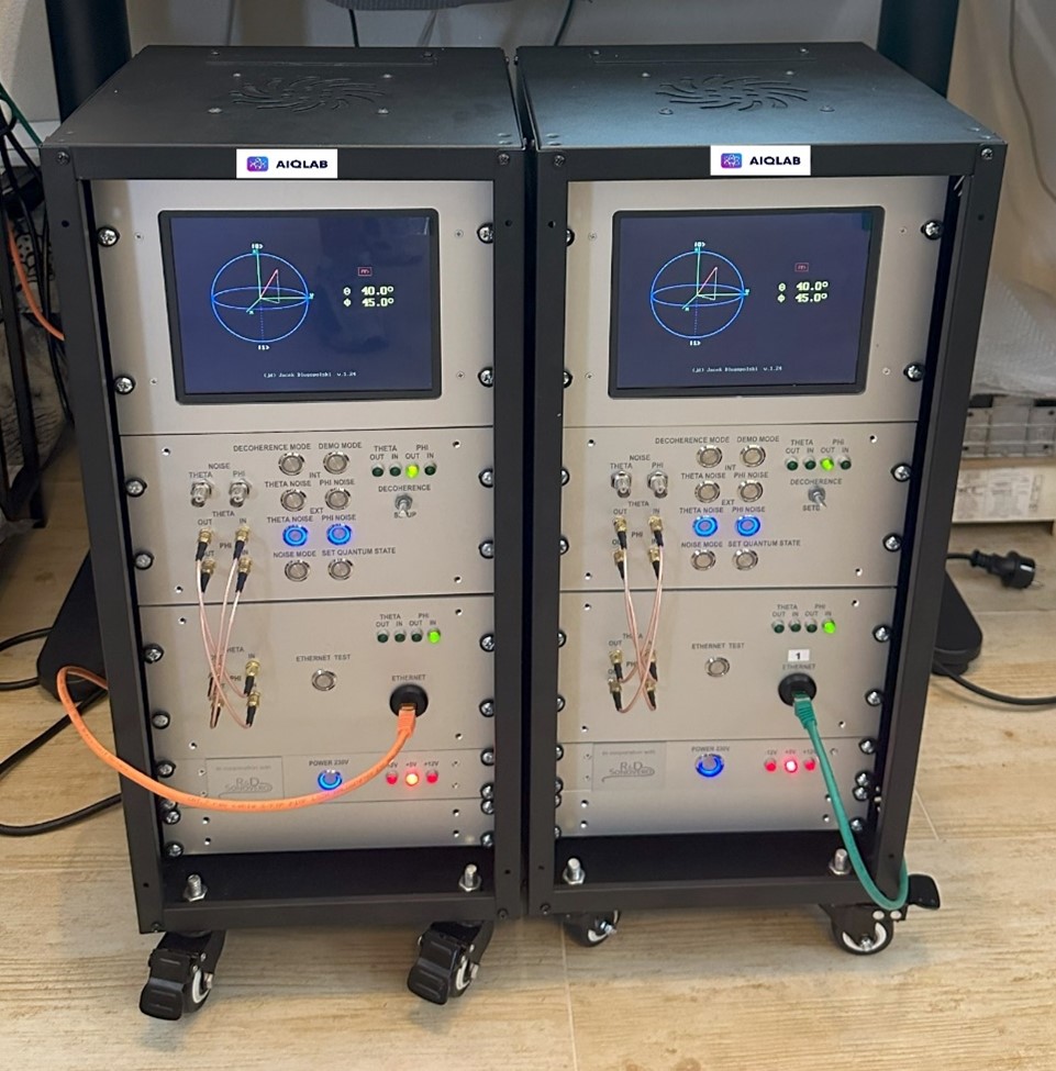
Physical Emulation of a Qubit’s State
QUBIT is an FPGA-based platform designed to control and emulate a quantum environment in real time. The behavior of the virtual qubit is displayed graphically on a Bloch sphere.
The state of the qubit is described by two angles: THETA (θ) and PHI (φ). The THETA angle determines the level of superposition, while the PHI angle determines the phase of the modeled qubit. As in real quantum systems, the values of these angles cannot be set directly – the user can only set the qubit’s initial state to |0⟩, and then, using a series of pulses of specific lengths, perform the appropriate rotations of the state vector to obtain the intended final state.
The user can change the state vector using digital pulses, observe the generated output signals, and monitor the phase, superposition, and the effect of disturbances.
- real-time operation and visualization,
- state control via digital pulses with an accuracy of 1 µs,
- continuous monitoring of qubit parameters,
- the ability to observe signals on an oscilloscope,
- functions for emulating internal and external noise as well as the decoherence phenomenon.
Optical Qubit Control System
The QUBIT emulator has been extended with a real, laser-based optical system that reproduces the optical control methods used in real ion traps. This makes it possible to explore the wide range of problems faced by designers and operators of quantum systems, even before they start building the actual hardware.
The optical system uses, among other things:
- a 532 nm DPSS (green) laser with a power of 300-500 mW,
- two acousto-optic modulators (AOMs) with their respective drivers,
- high-speed Hamamatsu S10317-1 light detectors,
- a programmable FPGA chip (the GENMET generator) controlling the AOM modulators.
The light emitted by the laser passes through an absorptive filter and then through a λ/2 half-wave plate, which sets the linear polarization. The light then passes through a polarizing beam splitter (PBS), the first modulator (AOM1), a λ/4 quarter-wave plate (converting the polarization to circular), and a collimating lens. The system operates in a double-pass configuration, allowing the laser beam to be switched on and off very quickly and precisely.
The second part of the system, built around the AOM2 module, is used to quickly address one of the two detectors connected to the control inputs of the QUBIT emulator – THETA or PHI. At any given time, only one parameter of the emulated qubit can be controlled.
Laser Pulse Control
Output channel OUT1 of the GENMET generator controls the AOM1 modulator and is used to key the laser beam in order to form pulses of light of the desired length, with an accuracy of one microsecond. Channel OUT2 controls the AOM2 modulator and is responsible for deflecting the beam to properly address the selected light detector.
For example, to set the qubit’s state to THETA = 46° and PHI = 75°, the emulator performs the following sequence:
- turning off the active signal to AOM1, to disable the laser beam in the double-pass circuit,
- turning off the active signal to AOM2, to set the THETA detector addressing,
- generating a light pulse with a duration of 9000-9100 µs, resetting the THETA angle to zero (the |0⟩ state),
- generating a 460 µs light pulse, changing the THETA angle by 46°,
- enabling the constant active signal to AOM2, to set the PHI detector addressing,
- generating a light pulse with a duration of 9000-9100 µs, resetting the PHI angle (the qubit’s phase) to zero,
- generating a 750 µs light pulse, changing the PHI angle by 75°.
This sequence is initiated via UDP packets sent from a Python script directly to the GENMET device controlling the AOM modulators.
Results and Control Accuracy
Tests of the laser-based control of the QUBIT emulator produced positive results, confirming the validity of the proposed concept. The pulses of laser light generated by the optical system allow the THETA and PHI angles to be changed with an accuracy of 0.1°, enabling any operation to be performed on the controlled qubit.
Achieving an angular precision of 0.1° requires a high-quality laser with minimal fluctuations, as well as thermal stability of all optical and electronic components. The system reaches full thermal stability approximately 15 minutes after power-up. It is also important to ensure low and stable external lighting, as it affects the operating thresholds of the optical sensors.
Future Development
The platform currently allows control of two parameters (THETA and PHI) of a single qubit, although only one of them can be controlled at any given time – due to the use of a single laser. Further development work is planned, aimed, among other things, at extending control to more than one qubit.
To achieve this, the AOM modulator currently used for detector addressing is planned to be replaced with an acousto-optic deflector (AOD), which allows the laser beam to be freely deflected over a wider range. This would make it possible to address a larger number of detectors – for example, addressing four detectors would allow independent control of two qubits, opening the way to testing multi-qubit quantum gates.
Scientific Publications
Publication in Computer Science – DOI: 10.7494/csci.2024.25.4.6289
“Optical control system for quantum bit emulator based on green laser, AOM modulators and FPGA technology” – DOI 10.24425/opelre.2025.157332